Example: Bathse Spuisluis
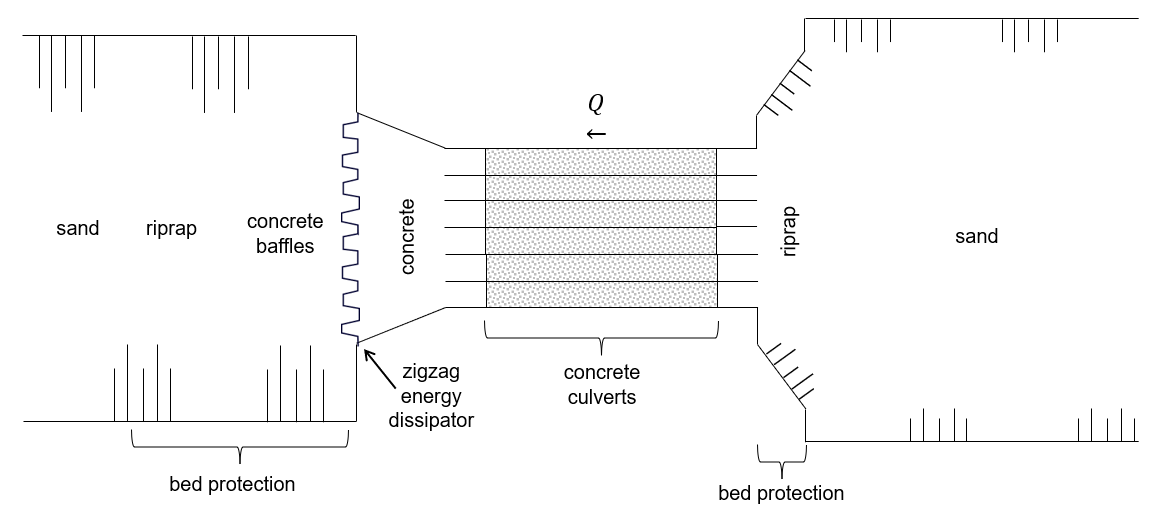
This example demonstrates the results of SPUIS4.02 by applying it to an as-built discharge sluice that is part of the Dutch Deltaworks: discharge sluice Bath (Dutch: ‘Bathse Spuisluis’). This discharge sluice is located at the end of a flushing channel (Dutch: ‘Bathse Spuikanaal’) between Lake Volkerak-Zoom and the Western Scheldt. It discharges surplus fresh water from the lake into the Western Scheldt to regulate Lake Volkerak-Zoom’s water level and to improve its water quality (flushing). The discharge sluice consists of six concrete culverts and has a maximum discharge capacity of 300 m³/s. A zigzag shaped energy dissipator (\(\mu\) = 0.7, see Tutorial) is located at the end of the outflow channel. A schematic top view of discharge sluice Bath is shown below. Areas shaded in grey have a ceiling.
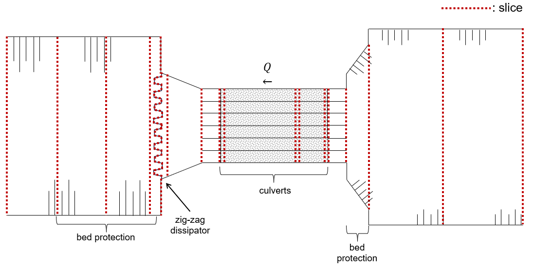
To capture the geometry of discharge sluice Bath [1] [2] and flushing channel [3], seventeen slices were defined. The Tutorial page explains how this schematization was set up using a few of the profiles as an example.
The result of schematizing discharge sluice Bath in SPUIS4.02 is shown below (black lines) for several configurations (meaning combinations of open/closed gates). The applied calculation method is 1 (Bernoulli and momentum equations). Shown along with the results are a set of field measurements (+) from 1988 [4] and calibrated calculations (o) used by Rijkswaterstaat (Directorate-General of the Ministry of Infrastructure and Water Management of the Netherlands) in their operational water management [5]. The configuration of each culvert is denoted by “O” for fully opened and “X” for closed. The SPUIS schematization shows good agreement with the field measurements and calibrated calculations.
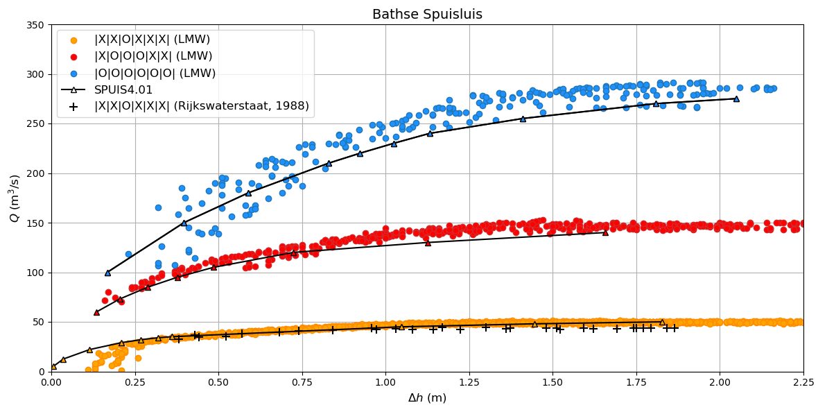
The input file for the schematization of one of Bathse Spuisluis’ culverts is shown below (corresponding to orange in the figure above). To extend this example to other possible configurations with more than one culvert in operation, the width and wetted perimeter of all profiles located in the culverts need to be extended.
    **###########################################################
    **Date		: 01-11-2024
    **Filename	: bath.in
    **Sluice	: Bathse Spuisluis
    **
    **Input file for program SPUIS version 4.02, July 2024.
    **Calculation of discharge relations of discharge sluices.
    **
    **Remark : Lines starting with '**' are for comments.
    **###########################################################
    **
    **
    **  BOUNDARY CONDITIONS
    **
    **  Calculation method        		bm  [-]
    **  0 = method backwater curves
    **  1 = method Bernoulli/momentum equation
    **
    1
    **
    **  Number of runs               	nr  [-]
    **  Minimum 1, maximum 100.
    **
    9
    **
    **  FOR EACH RUN:
    **
    **  downstream water level         	wsbe  [m]
    **  flow rate	                    qt    [m3/s]
    **
    **  Column 1	Column 2
    **  wsbe		qt
    **
    -0.10 5
    -0.15 12.5
    -0.20 22
    -0.30 29
    -0.40 32
    -0.50 34
    -0.60 35
    -0.80 45
    -1.00 48
    **
    **
    **  GEOMETRY OF SLUICE
    **
    **  The geometry of the sluice is defined by slices in the
    **	longitudinal direction of the sluice. The relevant slices
    **	need to be defined here.
    **
    **
    **  EXAMPLE top view of sluice:			           +++++++++++++++++++++
    **                                              +
    **  ++++++++++++++++++++++++++                  +
    **                           ++++++++++++++++++++
    **                           |||||||||
    **  |-------------------------------------------------------------------> X
    **                           |||||||||
    **                           ++++++++++++++++++++
    **  ++++++++++++++++++++++++++                  +
    **                           ^         ^      ^ +
    **   ^                    ^  |         |      | +++++++++++++++++++++
    **   |                    |  |         |      |  ^                 ^
    **   |                    |  |         |      |  |                 |
    **   |                    |  |         |      |  |                 |
    **   1  <----slices---->  2  3         4      5  6                 7
    **
    **
    **  A slice defines a change in lateral profile and a section
    **	of the sluice for which a discharge relation exists.
    **	Define number of slices minimum 2, maximum 50.
    **
    **  Number of slices				nx  [-]
    **
    17
    **
    **  FOR EVERY SLICE:
    **
    **  slice number					id  [-]
    **  X-distance						xd  [m]
    **  Bottom level					zb  [m]
    **  Profile number					pn  [-]
    **
    **  Define slices with increasing number!
    **
    **  Column 1	Column 2	Column 3		Column 4
    **  id-number	X-distance	Bottom level	Profile number
    **  id			xd			zb				pn
    **
    1 -250.0 -7.0 1
    2 -130.0 -7.0 1
    3 -30.0 -7.0 2
    4 0.0 -6.0 3
    5 5.0 -4.25 4
    6 5.1 -5.00 5
    7 29.9 -5.00 5
    8 30.0 -5.35 13
    9 61.9 -5.35 6
    10 62.0 -6.00 7
    11 65.0 -6.00 8
    12 86.55 -6.00 14
    13 86.65 -3.50 9
    14 87.00 -8.00 10
    15 102.00 -8.00 11
    16 187.0 -8.00 12
    17 270.0 -8.00 12
    **
    **
    **  FOR EVERY SLUICE SECTION:
    **
    **	A section of the sluice is the part between 2 slices.
    **	There are nx-1 sections.
    **
    **  Discharge relation				ar  [-]
    **  No longer serves a purpose as of SPUIS 4.01 - use discharge relation 0 (nx-1) times.
    **
    0 0 0 0 0 0 0 0 0 0 0 0 0 0 0 0
    **
    **
    **  DESCRIPTION PROFILES
    **
    **	The geometry of a slice is described using a profile.
    **	Define number of profiles minimum 2, maximum 20.
    **
    **  Number of profiles				np  [-]
    **
    14
    **
    **  FOR EVERY PROFILE:
    **
    **	A profile has an identification number (profile number).
    **	The number of corner points (y-values) has to be entered
    **	for every profile. At minimum 2 and maximum 20.
    **	The roughness has to be entered for every profile, this
    **	then holds for the entire profile. The roughness is defined
    **	as a Nikuradse k-value. For every corner point a height
    **	level relative to the bottom level has to be entered (>0).
    **	For every corner point of every profile a width of the
    **	water surface has to be entered. For every corner point the
    **	wet perimeter (for a water level at this level) has to be
    **	entered.
    **
    **	Order for every profile:
    **	1 row with 3 number
    **		profile number				ip  [-]
    **		number of points			ny  [-]
    **		roughness					rb  [m]
    **  ny rows with 3 number
    **     level of each point			dp  [m]
    **     width at each point			bp  [m]
    **     wet perimeter at each point	op  [m]
    **
    **
    **	Enter the profile in increasing order!
    **
    **  profile 1 (upstream canal with sandy bed)
    **
     1 6 0.01
     0.00 0.00 0.00
     0.01 65.00 65.00
     6.50 117.00 118.60
     6.51 127.00 128.60
     7.50 133.00 134.92
     7.51 143.00 144.92
    **
    **
    **  profile 2 (bed protection in upstream canal)
    **
     2 3 0.6
     0.00 0.00 0.00
     0.01 55.00 55.00
     7.00 111.00 122.72
    **
    **
    **  profile 3 (pillars in front of culverts, C=0.59)
    **
     3 3 0.6
     0.00 0.00 0.00
     0.01 2.80 1.65
     6.50 2.80 9.32
    **
    **
    **  profile 4 (sill in culverts)
    **
     4 4 0.002
     0.00 0.00 0.00
     0.01 2.80 2.80
     4.75 2.80 12.30
     4.76 0.00 15.10
    **
    **
    **  profile 5 (culverts, before gate)
    **
     5 4 0.002
     0.00 0.00 0.00
     0.01 2.80 2.80
     5.50 2.80 13.80
     5.51 0.00 16.60
    **
    **  profile 6 (culverts, after gate)
    **
     6 4 0.002
     0.00 0.00 0.00
     0.01 2.80 2.80
     5.85 2.80 14.50
     5.86 0.00 17.30
    **
    **  profile 7 (pillars behind culverts, C=0.65)
    **
     7 3 0.002
     0.00 0.00 0.00
     0.01 2.80 2.80
     6.50 2.80 15.80
    **
    **  profile 8 (stilling basin, near culverts)
    **
     8 3 0.002
     0.00 0.00 0.00
     0.01 25.00 25.00
     7.00 25.00 39.00
    **
    **  profile 9 (zigzag energy dissipator, mu = 0.7)
    **
     9 3 0.002
     0.00 0.00 0.00
     0.01 30.46 30.46
     2.50 30.46 33.96
    **
    **  profile 10 (concrete blocks - bed protection)
    **
     10 3 0.002
     0.00 0.00 0.00
     0.01 57.00 57.00
     11.00 145.00 147.71
    **
    **  profile 11 (riprap - bed protection)
    **
     11 3 0.6
     0.00 0.00 0.00
     0.01 57.00 57.00
     11.00 145.00 147.71
    **
    **  profile 12 (outflow channel)
    **
     12 3 0.01
     0.00 0.00 0.00
     0.01 57.00 57.00
     11.00 145.00 147.71
    **
    **  profile 13 (culverts near rebates and gate recess, C = 0.76)
    **
     13 4 0.002
     0.00 0.00 0.00
     0.01 2.80 2.128
     5.85 2.80 10.49
     5.86 0.00 12.62
    **
    **  profile 14 (stilling basin, near zigzag dissipator)
    **
     14 3 0.002
     0.00 0.00 0.00
     0.01 43.52 43.52
     7.00 43.52 57.52